Nine Phase Motor Controller
Over the summer, I had the privilege of participating in the PowerWheels Racing Series. Think back to the little toy cars 5 year olds rode in made of plastic and hot rod dreams.
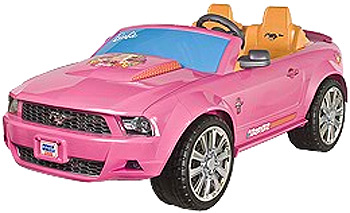 Barbie has more horsepower than you
The PowerWheels series consists of racing go-karts made out of these Fisher Price Power Wheels, for under $500. Recently, it graduated to turning the kid cars into autonomous go-karts, with a steering linkage driven by a servo and a very-not-cheap LIDAR camera. Not surprisingly, it is difficult to find a high current servo controller that isn’t terribly expensive. In addition to the servo, one also needs drive motors, throttle, etc which can builds up to a fair amount of electronics. All together, a go-kart driven off of brushless motors and a DC servo has 3 separate motor controllers, with a total of 8 half bridges.
This year, I had the following idea: What if you just had one board, with all of your power electronics, on one board? And Nine Phase was born.
The Controller
Nine Phase is three three phase motor controllers, to control 3 brushless motors, with the ability to convert and of the individual controllers into an H bridge configurations. (Credits to Bayley Wang for his extensive help in this endevour). Of course, you could also go and use all of the phases together to make a nine phase controller, hence the name. Its uses could be autonomous gokart, 3 omniwheel drive robot, battlebot with two drive motors and weapon motor, etc.
Important Parts List:
- DVR8302 - Gate Driver
- Arduino Pro Mini - Logic
- PSMN7R0-100PS 100V 100A 6.8 mOhm MOSFET
The DVR8302 is a beautiful chip. It features a current sense amplifier, automatic overcurrent shutoff, a buck converter (on a completely separate die within the chip!) and low side PWM generation. Because it’s so complex, was a pain to work with. It’s difficult to debug, hard to solder correctly without a microscope, and sometimes just exhibits off behavior due to current protection. It’s worth the extra hassle in having a compact driver and the possibility of a fairly advanced controller.
In later revisions, the controller will implement current sensing as well as proper overcurrent protection. For version one however, the goal was simply three turning motors.
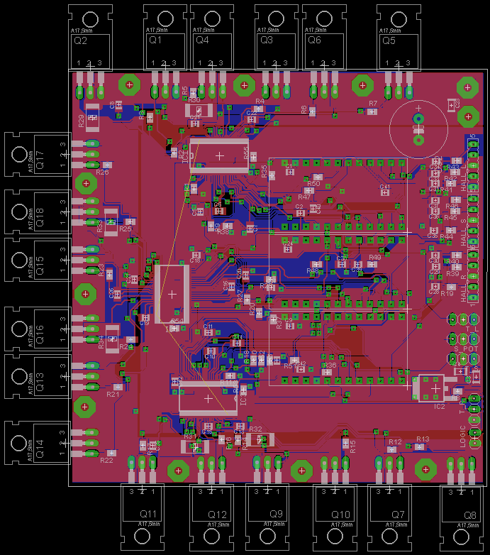 Version 1 Layout, with the drain and source switched on the MOSFETs.
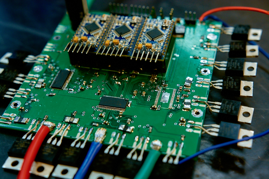
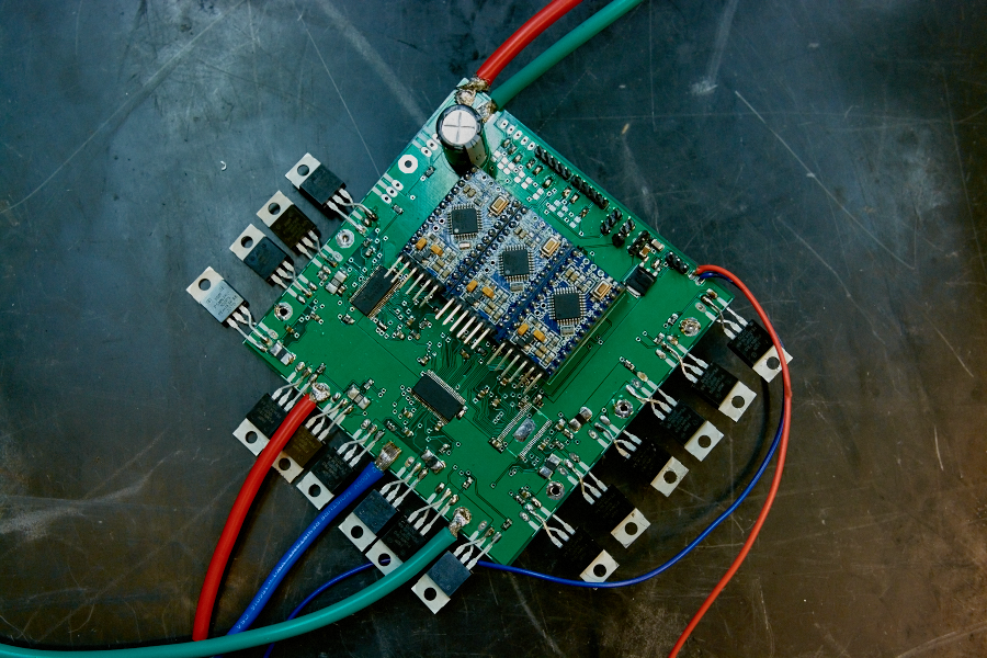 Version 1 board
The first version worked with only two hand-soldered wires, working up to ~30V. Above 30V, the motor controller would explode from bus rail noise. But, it turned brushless motors as well as doing position control on a gearmotor. That means it works, right?
Future Revisions
- Switch D and S on MOSFETs
- Move Throttle pins to Analog Inputs
- Current sense in code
- CW rotation support
- Better wire layout
You can find the Eagle files and Arduino code on my Github. Protected under MIT License.